

The Lesotho Highlands Water Project (LHWP) is more than a collection of dams.
It is an interconnected infrastructure system designed to capture water in Lesotho’s mountainous highlands, transfer it through reservoirs and tunnels, generate hydroelectricity and deliver supplies to South Africa.
Established under a treaty signed by Lesotho and South Africa in 1986, the project has been developed in phases.
Its first phase delivered major dams, water-transfer tunnels and the Muela hydropower station.
Phase II is extending that infrastructure through the construction of Polihali Dam and a new tunnel connecting its reservoir to Katse.
Building the system required engineers to work with steep valleys, basalt geology, remote construction sites and complex underground waterways.
The resulting structures illustrate how dam engineering, quarrying, tunnelling, concrete production and large-scale logistics come together in a single infrastructure programme.
1. Katse Dam: Building a concrete arch between mountains
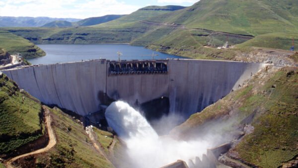
Katse Dam became one of the defining structures of Phase I. Located on the Malibamatso River, downstream of the confluence with the Bokong River, it was designed as a double-curvature concrete arch dam.
Completed in May 1997, the dam rises 185 metres above its foundation. Its crest extends approximately 710 metres, while its reservoir has a reported storage capacity of about 1.95 billion cubic metres.
The arch design allows the structure to transfer much of the water pressure laterally into the surrounding valley walls.
This makes the quality and stability of the abutments — the rock formations supporting either end of the arch — central to the dam’s safety.
Construction began in February 1991. Before the main wall could be raised, engineers had to prepare the foundation, establish suitable access and aggregate-processing facilities, and divert the river away from the work area.
A 35-metre-high upstream cofferdam was built to help divert river flows through two diversion tunnels.
This created a controlled area in which the dam foundation and main structure could be constructed.
Foundation excavation revealed rock conditions that prompted a conservative modification to the design.
Engineers incorporated a 165-metre-long preformed joint at the upstream heel of the dam, intended to reduce uplift pressures and increase the effective normal load on the structure.
The decision illustrates how construction-stage geological investigations can influence the final engineering solution, even after the main design has been developed.
The logistics behind the concrete
Producing the concrete required a dependable supply of suitable aggregate.
According to the Lesotho Highlands Development Authority (LHDA), basalt aggregate was quarried in a neighbouring valley and transported on a 2.4-kilometre conveyor belt that passed through a 1.4-kilometre tunnel before reaching a tertiary crusher near the concrete batching plant.
This arrangement reduced dependence on repeated truck movements between the quarry and the production area.
It also shows how aggregate processing and material-handling systems become major engineering operations in their own right on large dam projects.
The completed dam contains approximately 2.4 million cubic metres of concrete. Galleries within the wall provide access for inspection and instrumentation, allowing engineers to monitor the structure’s behaviour and manage seepage.
The Katse project demonstrates that constructing a major concrete dam involves much more than pouring concrete.
Foundation treatment, aggregate quality, batching, transport, placement, cooling and long-term monitoring all contribute to the finished structure.
2. Mohale Dam: Turning quarried rock into a reservoir wall
The second major dam in Phase I used a different construction approach.
Mohale Dam, completed in 2002, is a 145-metre-high concrete-faced rockfill dam. Unlike Katse, where the main structure is concrete, Mohale relies on a large embankment of compacted rock, sealed on its upstream face with concrete.
The difference is fundamental to how the two dams were built.
For Mohale, engineers needed to source, process and place enormous quantities of rock in carefully controlled layers.
The rockfill had to be compacted to meet the project’s engineering requirements, while the concrete face provided the principal barrier against seepage through the embankment.
LHDA records describe how a basalt hill within the dam basin was crushed to provide construction material.
In effect, material excavated from the surrounding landscape became a major component of the dam itself.
This method places substantial demands on quarrying equipment, crushers, haul trucks, earthmoving machinery and compaction equipment.
Material grading, moisture conditions, layer thickness and compaction quality are important because the embankment must perform as an engineered structure rather than simply a mass of dumped rock.
Mohale’s reservoir has a reported capacity of approximately 947 million cubic metres. The dam is connected to Katse Reservoir by an approximately 32-kilometre tunnel, allowing water to move between the two reservoirs as required by the system’s operating arrangements.
The project therefore combines two distinct dam-construction philosophies: a concrete arch at Katse and a concrete-faced rockfill embankment at Mohale.
Together, they demonstrate how site conditions and engineering requirements can lead to different structural solutions within the same water infrastructure programme.
3. Tunnelling through the mountains
The dams provide storage, but the project depends on tunnels to move water between reservoirs and towards South Africa.
One of the key Phase I structures is the approximately 45-kilometre Katse–Muela transfer tunnel. It carries water from Katse Reservoir towards the Muela hydropower station.
The tunnel includes an intake tower at Katse, with intake openings at different depths. This arrangement allows operators to select water from different reservoir levels, depending on operating conditions.
The original design called for concrete lining along at least six kilometres of the tunnel. However, instability encountered in the exposed basalt led engineers to adopt a more extensive solution: lining the full tunnel with approximately 300 millimetres of concrete.
That decision increased the lining work required but provided additional structural support.
The wider Phase I tunnel network also includes the delivery tunnels carrying water from the Muela system towards South Africa and the approximately 32-kilometre interconnecting tunnel between Mohale and Katse.
Tunnel excavation methods varied with the geology and the requirements of individual sections.
Tunnel-boring machines were used on parts of the delivery system, while drill-and-blast techniques were used elsewhere.
A tunnel-boring machine excavates rock mechanically with a rotating cutting head.
Depending on the machine and ground conditions, supporting systems behind the cutterhead can remove spoil, install lining and provide the infrastructure needed to advance through the mountain.
Drill-and-blast construction follows a different sequence.
Crews drill holes into the rock, load controlled explosive charges, blast the excavation face, remove the broken material and install ground support as required. Rock bolts and sprayed concrete can help stabilise the exposed excavation.
The choice between methods depends on factors including geology, tunnel geometry, excavation length, groundwater conditions and construction logistics.
For the LHWP, these underground works were not isolated civil engineering structures. They formed the connections that made the dams function as a coordinated regional water-transfer system.
4. Muela: Generating electricity on the water’s journey
The LHWP was also designed to generate hydroelectricity for Lesotho.
At Muela, water travelling from Katse passes through a hydropower station equipped with three 24-megawatt turbine-generators, giving the installation a combined capacity of 72 MW.
The powerhouse is underground, housed in a cavern excavated to accommodate the generating equipment and associated electrical infrastructure.
Water under pressure passes through the turbines, driving generators that produce electricity.
After leaving the turbines, the water travels through downstream hydraulic structures and continues along the delivery system towards South Africa.
Integrating the power station into the water-transfer route was a central feature of Phase I. It allowed Lesotho to generate electricity from the infrastructure used to transfer water across the border.
The engineering challenge extended beyond installing turbines. The station required underground excavation, hydraulic passages, surge-management arrangements, electrical equipment, controls and a reliable connection between the waterway and the delivery tunnels.
Muela illustrates how a major water project can combine several infrastructure functions within one interconnected system.
5. Polihali: Extending the system with a new rockfill dam
The latest major expansion is taking place under Phase II, centred on Polihali Dam and the Polihali–Katse transfer tunnel.
Polihali is being constructed downstream of the confluence of the Senqu and Khubelu rivers. Like Mohale, it is designed as a concrete-faced rockfill dam.
LHDA specifies an embankment approximately 166 metres high, with a crest length of about 921 metres and a crest width of nine metres.
More than 14 million cubic metres of rock are expected to be compacted to form the main embankment.
The reservoir is designed to hold approximately 2.325 billion cubic metres of water at full supply level.
Construction involves quarrying and processing rock, transporting it to the embankment, placing it in controlled layers and compacting it to meet engineering specifications.
The upstream concrete face provides the water barrier, while the rockfill embankment supplies the main structural mass.
The dam also includes associated structures such as a spillway and outlet works. A separate saddle dam will close a low point around the reservoir perimeter to prevent water from escaping around the main dam.
The scale of the rockfill operation makes material management central to construction.
Quarry production, crushing, haulage routes, placement rates, compaction equipment and quality control all need to work in coordination to maintain progress while meeting design requirements.
Diverting the Senqu River
Before the main dam could be constructed across the river valley, engineers needed to redirect river flows around the foundation area.
Two diversion tunnels were excavated through the rock. One is approximately seven metres in diameter and the other approximately nine metres; each is nearly a kilometre long.
The tunnels were excavated using drill-and-blast methods, with rock bolts and sprayed concrete installed where required to support the excavated rock.
Diversion tunnels are critical temporary works. By routing the river away from the dam footprint, they help create the conditions needed to prepare foundations and construct the embankment.
Their capacity and configuration must also account for river flows and flood conditions during construction.
The Polihali diversion tunnels were completed in 2021, ahead of the main dam construction contract.
6. Boring the 38-kilometre Polihali–Katse tunnel
The second major Phase II component is a transfer tunnel connecting Polihali Reservoir to Katse Reservoir.
The tunnel is approximately 38 kilometres long and has a nominal bore of about five metres.
Once operational, it will allow water from Polihali to flow by gravity towards Katse, integrating the new reservoir into the existing transfer network.
Two tunnel-boring machines are working from opposite ends of the alignment.
Their excavation progress depends on underground geology, ground stability and the ability to maintain the machines and their supporting systems.
In an October 2025 project update, LHDA described the second machine as approximately 305 metres long and 5.35 metres in diameter.
The machine’s length reflects the complexity of the complete tunnelling system, which includes the cutterhead, equipment for removing excavated material and backup gantries carrying supporting systems.
The tunnel works also require intake and outlet structures, gate shafts, access adits and construction facilities.
Ground conditions remain a significant variable.
In September 2026, South Africa’s water minister reported that geological challenges had slowed tunnel excavation. The official update put the tunnel at 58% completion and overall Phase II construction at 56.7%.
Those figures are a snapshot of progress at the time of the September visit, not a measure of the project’s present-day completion.
7. Building the roads and bridges behind the dam
A dam and transfer tunnel cannot be built in isolation. Construction crews need roads to transport machinery, fuel, aggregate, concrete materials, equipment and personnel into the project area.
Phase II therefore includes access roads, major bridges, electricity supply, telecommunications, accommodation and other supporting facilities.
The Senqu Bridge is one of the most prominent examples. Opened to traffic in 2026, it improves connectivity in an area where the mountainous landscape creates substantial challenges for transport and construction logistics.
Access roads provide routes for heavy vehicles, while quarries and borrow pits supply the materials needed for embankments, roads and concrete works.
Site offices, workshops and accommodation support the workforce and the operation of specialised machinery.
These facilities may not have the visual prominence of a dam wall, but they are essential to the delivery of a remote megaproject.
Without reliable access and utilities, the movement of construction materials and the maintenance of heavy equipment would be considerably more difficult.
8. What comes next?
Phase I of the Lesotho Highlands Water Project was completed in 2003 and inaugurated in 2004. Phase II is intended to increase the volume of water transferred to South Africa.
According to the September 2026 progress update, Polihali Dam was 53% complete and the overall second phase had reached 56.7%.
Water impoundment at Polihali was expected to begin in July 2027, subject to construction progress and project requirements.
Once the new system is operational, the planned annual water transfer to South Africa is expected to rise from approximately 780 million cubic metres to around 1.27 billion cubic metres.
The expansion demonstrates how large water projects evolve over decades.
Engineers are not simply building another dam: they are extending an existing system whose performance depends on reservoirs, tunnels, power generation, delivery infrastructure and coordinated operation across an international border.
For the construction industry, the project brings together several disciplines at scale: concrete dam engineering, rockfill construction, quarrying, tunnel boring, geotechnical investigation, hydropower, heavy transport and infrastructure logistics.
The completed Phase I structures and the ongoing work at Polihali reveal the same underlying principle.
A major water-transfer project is only as effective as the engineering connections between its individual components.
Sources: Lesotho Highlands Development Authority, Phase I and Phase II technical project pages; LHDA, Progress Update: Polihali Transfer Tunnel – Second TBM Steps In (October 2025); South African Government News Agency, Majodina welcomes LHWP Phase 2 progress towards 2027 impoundment (15 September 2026).
Also Read
- How They Were Built: Inside the Construction of the Grand Ethiopian Renaissance Dam
- How They Were Built: Engineering Christ the Redeemer
- How They Were Built: Inside the Burj Khalifa

- How They Were Built: Inside the Engineering of the Lesotho Highlands Water Project - October 11, 2026
- Africa’s Water Reuse Opportunity: Building the Infrastructure for a Water-Secure Future - September 28, 2026
- Why Water Reuse Is Becoming a Business Imperative for African Industry - September 28, 2026